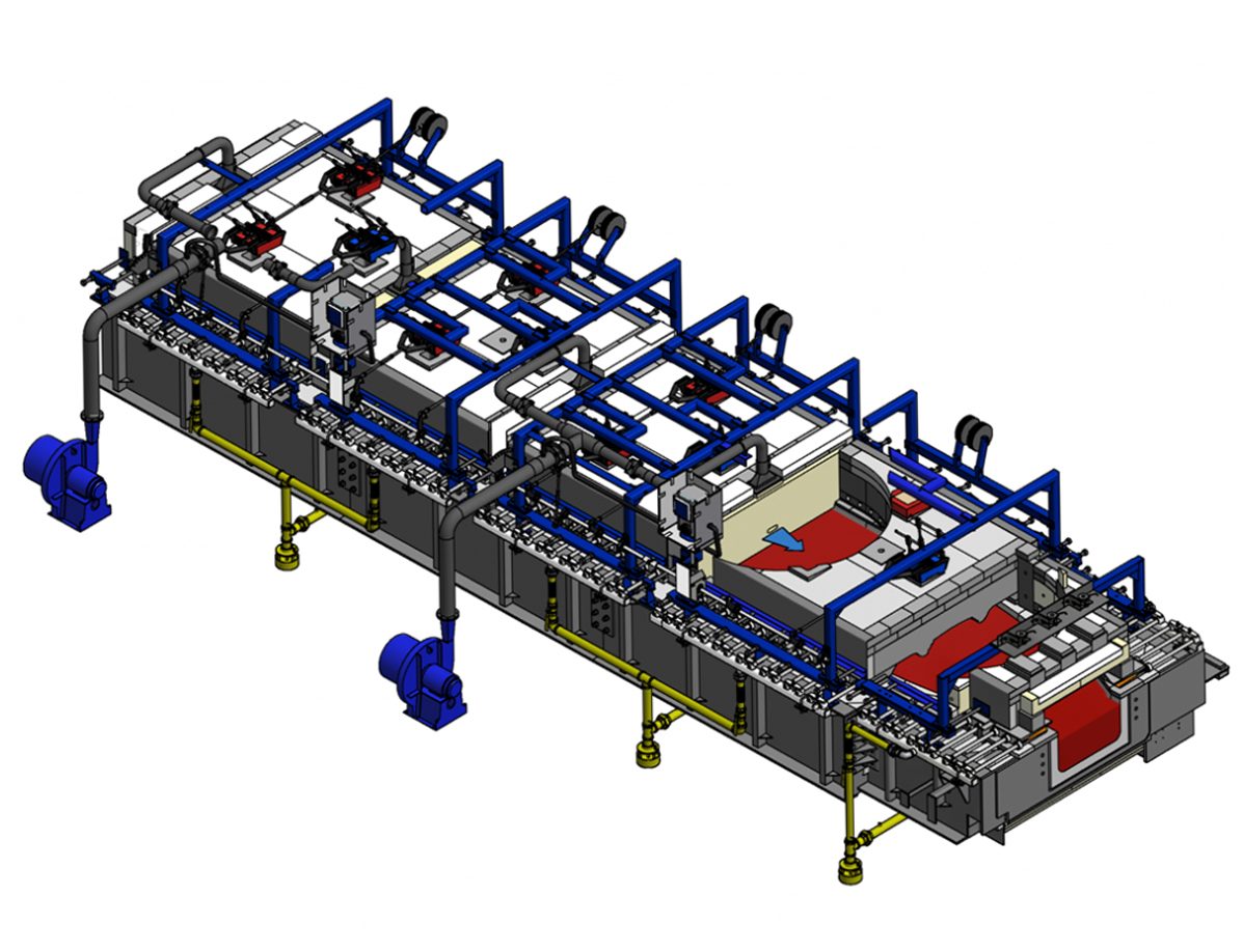
System 500 Forehearth
& Distributor
Designed to achieve the best glass thermal
homogeneity and energy over the widest operating range.
Designed to achieve the best glass thermal
homogeneity and energy over the widest operating range.
It is critical that glass presented to the forming machine is thermally homogeneous, thermally stable and at the correct temperature for the forming process. The design of the forehearth and distributor is crucial to achieving these requirements.
The System 500 forehearth was specifically designed to achieve the best glass thermal homogeneity over the widest operating range with optimum fuel efficiency and with more than 500 worldwide installations to date its ability to achieve these objectives is well proven.

The roof block geometry used in System 500 technology divides the forehearth into three lateral chambers. The central chamber is used as a conduit for a longitudinal, forced convection cooling system in which cooling air is injected into the forehearth chamber at the start of each cooling zone and exhausted through a central flue at the end of the zone. The cooling air flow rate and position of the exhaust damper are automatically controlled. This allows the forehearth to ensure a positive internal forehearth pressure is maintained. In addition the forehearth is configured with side flues which, when operating in cooling mode, allow the combustion gases to exhaust from the forehearth without entering the central cooling section. These exhausts are also fitted with automatically controlled damper blocks.
By containing cooling in the central chamber of the forehearth and heating in the side chambers of the forehearth we target the heating and cooling functions where they are required therefore cooling the central hot stream of glass and heating the cooler streams of glass at the sides of the forehearth to overcome heat losses through the channel side walls. Also, by ensuring cooling and combustion functions remain separate inside the forehearth, we maximise the combustion and cooling efficiency.
When the system is operating in heating mode, the cooling air control valve and side dampers are closed automatically. This forces the combustion gases into the centre of the forehearth to exhaust through a small notch in the central cooling damper block therefore inputting heat into the glass across the entire forehearth width and allowing the forehearth to react to any changes in operating conditions. However, the profile design of the roof block re-radiates heat from the burners back towards the channel side walls, and the closure of the combustion dampers prevents any heat loss to atmosphere, allowing preferential heating of the side streams of glass.
The PSR concept of sub-zoning also works to maximise the effect of the cooling system. By introducing two cooling air inlets and two cooling air exhausts in each zone, we halve the path length of the cooling air in the forehearth, optimising use of the cooling air volumes and minimising the possibility of overcooling the glass surface at the cooling air inlet point.
The distributor is a vital component of the glass conditioning process. The achievement of good glass thermal homogeneity before the glass enters the forehearth reduces the reliance on forehearth conditioning and improves the flexibility and production efficiency of the whole glass conditioning system.
By viewing the distributor as an extension of the forehearth, not the furnace, we can provide all the advantages of the System 500 forehearth throughout the glass conditioning process.
If required, higher cooling rates can be achieved with the installation of ‘Transverse Pressurised Radiation Cooling’ over the throat riser and ‘Triple Jet Longitudinal Cooling’ in adjacent cooling zones. ‘Pressurised Radiation Cooling’ is used over the throat riser area. As cooling is required the radiation cooling dampers move to the open position and cooling air is introduced automatically from side entry flue blocks. The glass surface radiates directly to atmosphere and is further cooled by radiation to the underside of the roof blocks. The cooling air also maintains the internal pressure inside the distributor.
‘Triple jet longitudinal Cooling’ is used in zones adjacent to the throat riser section. As cooling is required the dampers move to the open position and cooling air is introduced through 3 outlet holes in a special vented mantle block. The cooling air cools the underside of the roof blocks across their entire width, enabling the glass surface to be cooled right across the distributor width. This ensures fast cooling rates without the intense cooling effect of radiation cooling to atmosphere.